1. Производот завршиview
The ZS-X11H and ZS-X11H V1 are DC6-60V 400W BLDC (Brushless DC) three-phase Hall motor controllers designed for efficient and precise motor drive applications. These modules support PWM signal input for speed control and offer robust performance with features like brake function and analog control.
Клучни карактеристики:
- Superior Efficiency & Longer Runtime: Operates with significantly less energy loss compared to brushed motors, converting more power into motion and extending battery life in portable applications.
- Enhanced Durability & Low Maintenance: No physical brushes to wear out or replace. This eliminates sparking, reduces friction, and ensures a longer operational lifespan with minimal maintenance required.
- High Performance with Precision Control: Delivers exceptional torque for its size and provides smooth, consistent power delivery. Enables precise speed control for demanding applications.
- Quiet, Cool, and Reliable Operation: The brushless design results in smoother and quieter performance with reduced vibration. Generates less heat for improved reliability and safety.
- Compact, Lightweight Powerhouse: Engineered with a high power-to-size ratio, offering robust performance in a compact and lightweight form factor, ideal for space-conscious designs.
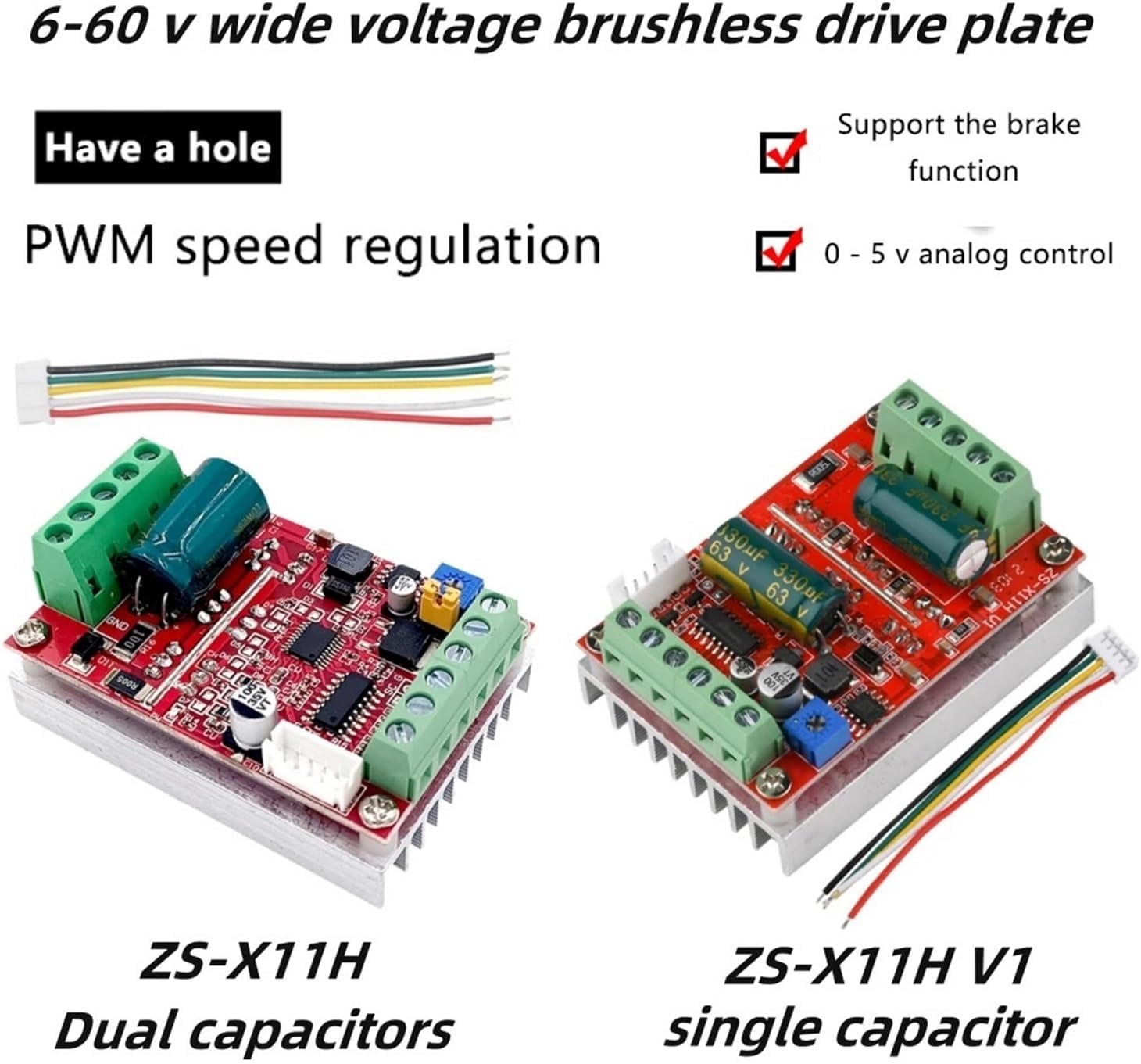
Figure 1: Comparison of ZS-X11H (dual capacitors) and ZS-X11H V1 (single capacitor) models. Both support 6-60V wide voltage, brake function, and 0-5V analog control, with PWM speed regulation.
2. Спецификации
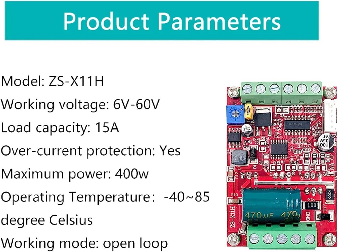
Figure 2: Detailed product parameters for the ZS-X11H model.
| Параметар | Вредност |
|---|---|
| Модел | ZS-X11H / ZS-X11H V1 |
| Работа Voltage | Еднонасочна струја 6V - 60V |
| Капацитет на носивост | 15 А |
| Заштита од прекумерна струја | Да |
| Максимална моќност | 400 W |
| Работна температура | -40°C до 85°C |
| Работен режим | Отворена јамка |
| Димензии на пакетот | 0.39 x 0.39 x 0.39 инчи (приближно) |
| Тежина на ставката | 3.53 унци |
| Потребни се батерии | бр |
3. Setup & Wiring
Careful wiring is essential for proper function and safety. Ensure all connections are secure and correct before applying power.
3.1 Општа шема за поврзување
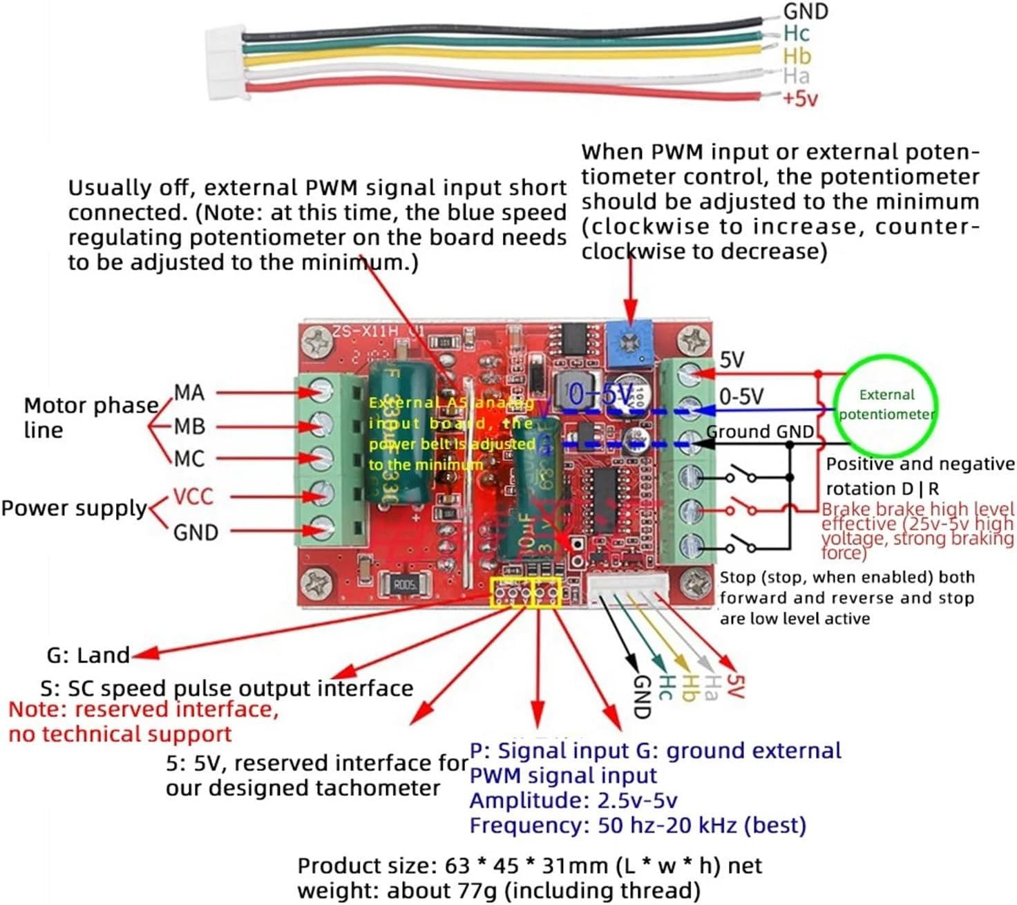
Figure 3: Detailed wiring diagram showing motor phase lines (MA, MB, MC), power supply (VCC, GND), 5V output, ground, PWM signal input (P), ground for external signal (G), speed pulse output (S), and Hall sensor connections (Hc, Hb, Ha, +5V, GND).
- Фазни линии на моторот: Connect MA, MB, MC terminals to the corresponding phase wires of your three-phase BLDC motor.
- Напојување: Connect DC 6-60V power to VCC (+) and GND (-) terminals.
- Хол сензор: Connect the motor's Hall sensor wires to the dedicated 5-pin connector: GND, Hc, Hb, Ha, +5V.
- PWM Signal Input (P): For external PWM speed control.
- Ground for External Signal (G): Connect to the ground of your external control signal.
- Speed Pulse Output (S): Reserved interface for tachometer or speed feedback.
3.2 Hall Motor Connection

Figure 4: Illustrates connecting the motor phase lines (MA, MB, MC) and the Hall sensor wires (GND, Hc, Hb, Ha, +5V) from the controller to a DC three-phase brushless motor with Hall sensors.
3.3 External Signal Speed Control Wiring
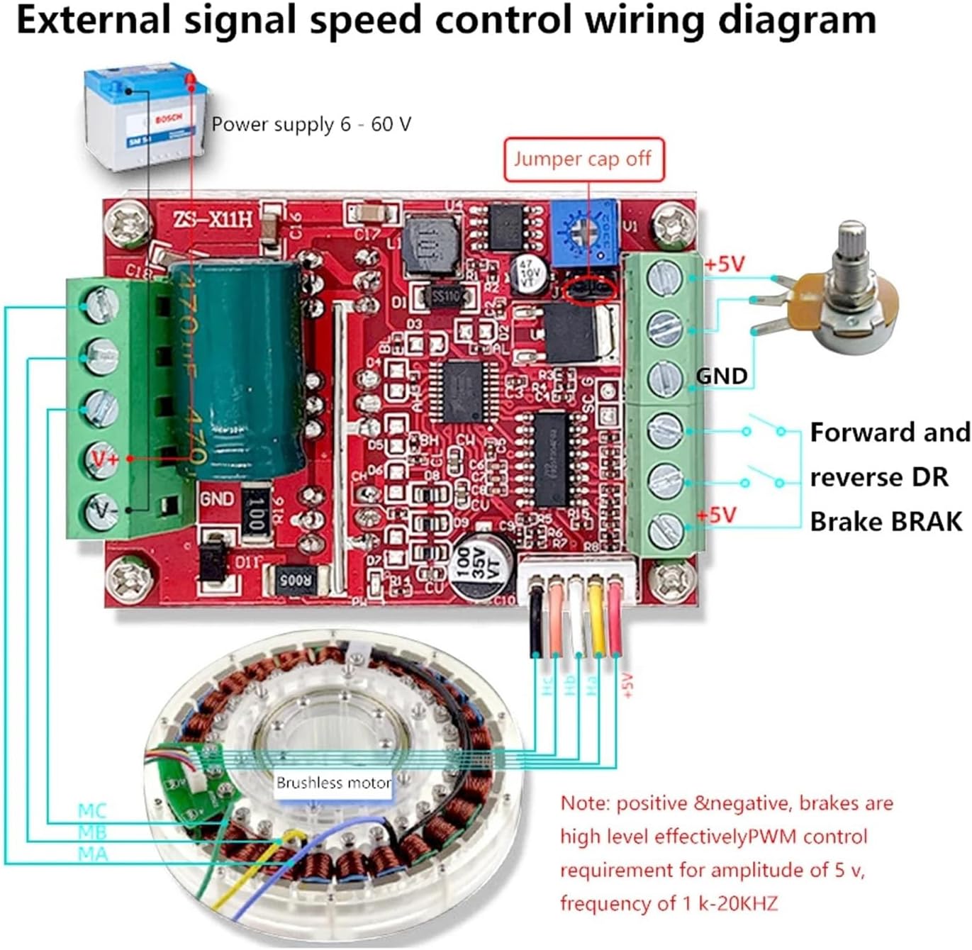
Figure 5: Shows wiring for external speed control using a potentiometer or PWM signal. Note the jumper cap position for selecting between onboard potentiometer and external control. Positive and negative brakes are high-level effective PWM control, requiring an amplitude of 5V and frequency of 1-20KHz.
- PWM Input: Connect your external PWM signal to the 'P' terminal and its ground to 'G'. The amplitude should be 5V, and frequency 1-20KHz for effective control.
- External Potentiometer: Connect the potentiometer as shown in Figure 5. The potentiometer should be adjusted to its minimum position (fully counter-clockwise) when using external PWM input.
- Jumper Cap: The jumper cap on the board allows selection between using the onboard potentiometer for speed control or an external PWM/voltage control. Remove the jumper cap for external control.
3.4 Hall Driven Plate Function Overview

Слика 6: Готовоview of the Hall driven plate functions, including connections for power supply, motor phases, Hall signals, 5V output, external PWM/voltage control, signal ground, reversing control, and brake control.
4. Операција
4.1 Контрола на брзина
- Onboard Potentiometer: If the jumper cap is in place, use the blue speed regulating potentiometer on the board to adjust motor speed. Turn clockwise to increase speed, counter-clockwise to decrease.
- External PWM/Analog Control: If the jumper cap is removed, connect an external PWM signal (5V amplitude, 1-20KHz frequency) or a 0-5V analog voltage to the 'P' terminal for speed control. Ensure the onboard potentiometer is set to its minimum position when using external control.
4.2 Контрола на насока
The controller supports forward and reverse operation. Connect a switch or control signal to the 'DR' terminal for direction control. Typically, a high or low signal will determine the direction.
4.3 Brake Function
The brake function is supported. Connect a control signal to the 'BRAK' terminal. A high-level signal (2.5V-5V) activates the brake, providing strong braking force.
5. Одржување
- Чистење: Одржувајте го модулот чист и без прашина и остатоци. Користете мека, сува крпа за чистење. Избегнувајте течности.
- Инспекција: Periodically inspect all wiring connections for looseness or damage. Ensure proper ventilation around the module to prevent overheating.
- Складирање: Чувајте го модулот на суво и ладно место кога не е во употреба.
6 Смена на проблеми
- Моторот не се врти: Check power supply connections, motor phase connections, and Hall sensor wiring. Verify that the speed control input (PWM or potentiometer) is active and correctly configured.
- Неправилно моторно однесување: Ensure Hall sensor wires are correctly connected and not swapped. Check for stable power supply. Verify PWM signal quality if using external control.
- Прегревање: Ensure the module is not overloaded beyond its 400W/15A capacity. Provide adequate ventilation.
- No Speed Control: If using external PWM, ensure the jumper cap is removed and the onboard potentiometer is at its minimum. Check the external PWM signal amplitude (5V) and frequency (1-20KHz).
7. Гаранција и поддршка
For warranty information, technical support, or service inquiries, please contact the manufacturer or your point of purchase. Keep your purchase receipt for warranty claims.


