Вовед
The System Sensor HR-LF is a low frequency sounder designed for indoor use in security and surveillance systems, specifically for sound detection and alarm output. This device is engineered to provide clear and effective audible alerts, crucial for life safety applications. This manual provides essential information for the proper installation, operation, and maintenance of your HR-LF sounder.
Информации за безбедност
Please read and understand all instructions before installing or operating the HR-LF sounder. Failure to follow these instructions may result in property damage, injury, or death. This device must be installed by qualified personnel in accordance with all local and national electrical and fire codes.
- Исклучете го напојувањето: Секогаш исклучувајте го напојувањето од струјното коло пред да го инсталирате, сервисирате или отстраните уредот.
- Правилно поврзување: Ensure all wiring connections are secure and comply with the wiring diagram provided with the device.
- Еколошки услови: Install the device in an environment that meets its specified operating conditions.
- Тестирање: Regularly test the device after installation and during routine maintenance to ensure proper operation.
Содржина на пакетот
Проверете дали сите елементи се присутни пред да започнете со инсталацијата:
- System Sensor HR-LF Low Frequency Sounder (Red)
- Монтажни материјали (завртки, сидра)
- Водич за инсталација (овој документ)
Поставување и инсталација
The HR-LF sounder is designed for surface mount installation. Follow these steps for proper setup:
- Изберете локација: Select an indoor location that provides optimal sound coverage and complies with local codes. Ensure the mounting surface is flat and secure.
- Подготовка на жици: Route the necessary electrical wiring to the chosen mounting location. Ensure power is disconnected before proceeding.
- Монтирање:
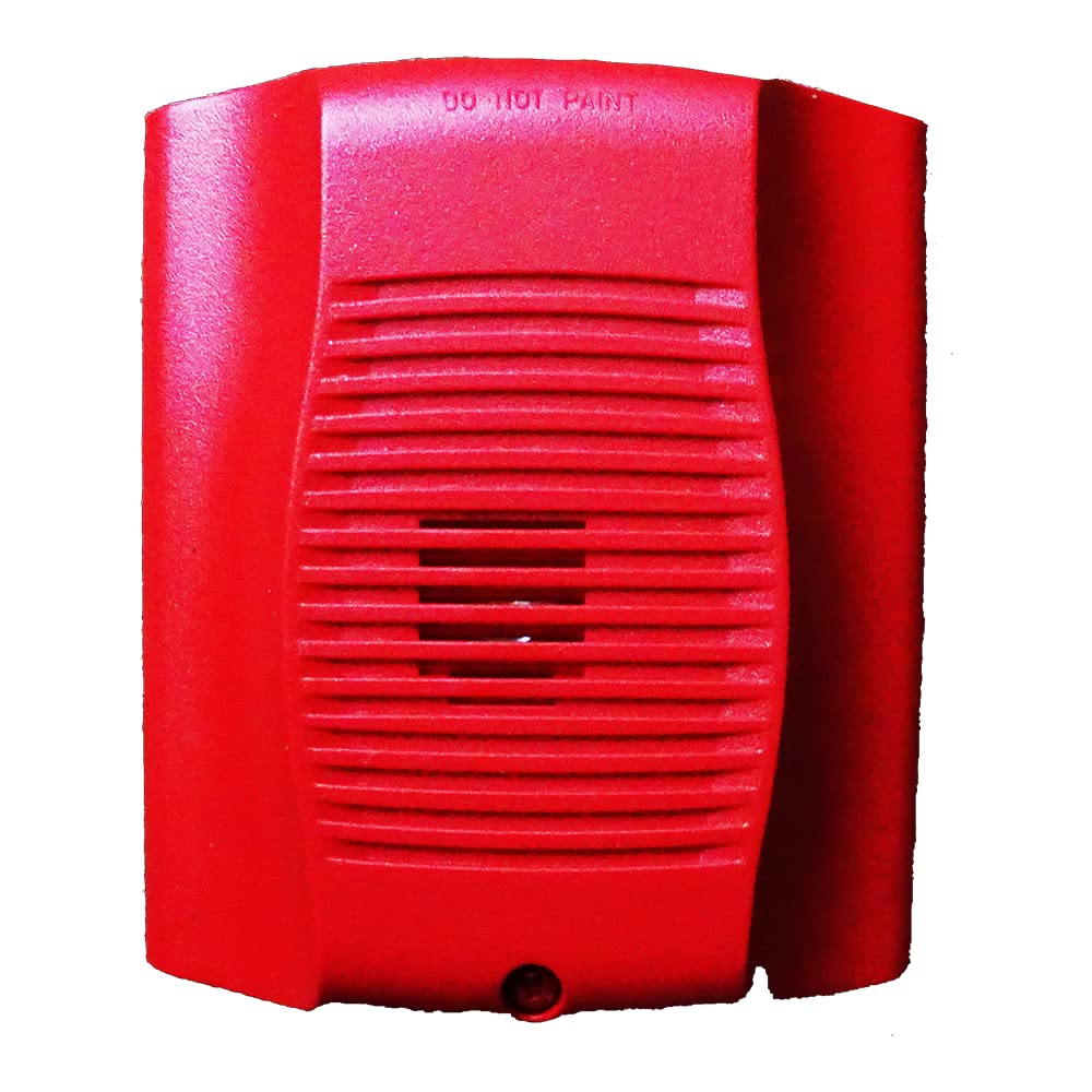
Слика: напред view of the System Sensor HR-LF low frequency sounder. This red device features a grille for sound emission and mounting points for surface installation.
- Position the sounder base against the wall or ceiling at the desired mounting point.
- Mark the locations for the mounting screws.
- Доколку е потребно, издупчете пилотски дупки и вметнете ѕидни типли ако монтирате во гипс картон.
- Secure the sounder base to the mounting surface using the provided screws.
- Приклучоци за жици: Connect the field wiring to the terminal block on the sounder base according to the wiring diagram provided with the device. Pay close attention to polarity.
- Attach Sounder Head: Once wiring is complete and secure, attach the sounder head to the mounted base, ensuring it locks into place.
- Вратете ја моќноста: After verifying all connections, restore power to the circuit.
- Тест операција: Perform an operational test as described in the "Operating Instructions" section.
Упатства за работа
The System Sensor HR-LF low frequency sounder operates as an alarm output device, typically activated by a connected fire alarm control panel or security system. It is designed to produce a distinct low-frequency tone for occupant notification.
- Активирање: The sounder will activate when it receives a signal from the connected control panel, indicating an alarm condition.
- Sound Pattern: The HR-LF typically produces a temporal 3 pattern (three short pulses followed by a pause), which is standard for fire alarm notification. Refer to your control panel's documentation for specific output patterns.
- Деактивирање: The sounder will deactivate when the alarm condition on the control panel is cleared or reset.
Note: The HR-LF is an output device and does not have user-configurable settings directly on the unit. All operational parameters are controlled by the connected fire alarm or security system.
Одржување
Regular maintenance ensures the continued reliable operation of your HR-LF sounder.
- Чистење: Periodically clean the exterior of the sounder with a soft, dry cloth to remove dust and debris. Do not use abrasive cleaners or solvents.
- Тестирање: Conduct periodic functional tests in accordance with local codes and manufacturer recommendations (typically annually) to ensure the sounder activates and produces the correct sound pattern.
- Инспекција: Visually inspect the device for any signs of damage, loose connections, or obstructions to the sound output.
Решавање проблеми
If your HR-LF sounder is not functioning as expected, refer to the following common issues and solutions:
| Проблем | Можна причина | Решение |
|---|---|---|
| Sounder does not activate. | Нема струја на уредот. Неправилно ожичување. Control panel not sending activation signal. | Проверете го напојувањето. Check wiring connections against diagram. Inspect control panel status and output. |
| Sounder activates intermittently. | Лабава врска со жици. Faulty control panel output. | Обезбедете ги сите жичени врски. Consult control panel manual or contact qualified technician. |
| Звукот е слаб или искривен. | Obstruction in front of sounder. Оштетување на уредот. | Исчистете ги сите пречки. Проверете за физички оштетувања; заменете го доколку е потребно. |
If troubleshooting steps do not resolve the issue, contact System Sensor technical support or a qualified service technician.
Спецификации
| Бренд | Системски сензор |
| Број на модел | HR-LF |
| Материјал | Пластика |
| Стил | Модерен |
| Тип на монтирање | Површинска монтажа |
| Тип на излез | Аларм |
| Специфична употреба | Indoor, Sound Detection |
| ASIN | B015NEAOB2 |
| Датум прв на располагање | 5 октомври 2016 година |
Гаранција и поддршка
System Sensor products are designed for reliability and performance. For specific warranty information, please refer to the warranty statement included with your product packaging or visit the official System Sensor website. For technical support, installation assistance, or service inquiries, please contact System Sensor customer service or your authorized distributor.
Контакт информациите обично може да се најдат на веб-страницата на производителот. webлокација или пакување на производот.


