1. Вовед
This user manual provides detailed instructions for the LINOVISION 24 Ports L2 Managed PoE Switch, Model POE-SW324GM-4BT. It covers product features, package contents, setup procedures, operating guidelines, maintenance tips, troubleshooting, and technical specifications. Please read this manual thoroughly before operating the device to ensure proper installation and functionality.

Слика 1.1: напред view of the LINOVISION 24 Ports L2 Managed PoE Switch.
2. Содржина на пакетот
Verify that all items listed below are included in your package. If any item is missing or damaged, please contact LINOVISION support.
- PoE Switch (POE-SW324GM-4BT)
- Адаптер за напојување
- Упатство за употреба
- Додаток за монтирање на решетката

Image 2.1: Contents of the LINOVISION PoE Switch package, including the switch, power adapter, user manual, and rack mount accessories.
3. Производот завршиview
3.1 Преден панел
The front panel of the LINOVISION POE-SW324GM-4BT features various ports and LED indicators for monitoring network activity and power status.

Слика 3.1: Детално view of the switch's front panel, highlighting the console port, 4x 90W Gigabit PoE ports (P1-P4), 20x 30W Gigabit PoE ports (P5-P24), and 4x Gigabit Combo ports (Uplink 1-4).
3.2 Заден панел
The rear panel includes the power input, power switch, and a ground terminal for safety.

Слика 3.2: Комбинирано view of the front and rear panels. The rear panel shows the power switch, ground terminal, and AC power input.
4. Карактеристики
- 4 BT 90W PoE++ Ports: Ports 1-4 support up to 90W output, providing sufficient power for IEEE 802.3af/at/bt compliant PoE devices such as IP cameras, PTZ cameras, access points, VoIP phones, and PoE monitors.
- Built-in 370W PoE Power Budget: The switch features a maximum total PoE budget of 370W, with 4 BT 90W ports and 20 AT 30W ports, capable of supporting multiple high-power PoE devices.
- Full Gigabit Connectivity: Provides 4x 10/100/1000Mbps PoE++ ports, 20x 10/100/1000Mbps PoE+ ports, and 4x Combo Ports. Each Combo Port includes one RJ45 port and one SFP port, allowing selection of either based on network requirements, but not both simultaneously.
- L2 Managed Capabilities: Supports Layer 2 management functions including VLAN, QoS, ACL, and PoE control (On/Off). Management can be performed via WEB interface, Command Line Interface (CLI), or SNMP.
- Advanced Safety for PoE and Non-PoE Devices: Utilizes a standard 4-step PoE power-up process (PD Detection -> PoE Power Classification negotiation -> Start up -> Power ON). This ensures appropriate power delivery to 802.3af/at/bt devices, preventing overloading, and avoids supplying power to non-PoE devices to prevent damage.
- Solid and Durable Design: Features a full metal enclosure with dimensions of 17.32'' x 11.42'' x 1.75'' (440mm x 290mm x 44.5mm), and a built-in 370W power supply. It offers a wide operating temperature range (-10°C to 45°C), 64Gbps switching capacity, IP40 protection, and 6KV surge protection.
- Important PoE++ Compatibility Note: The term "PoE++" does not have a single unified standard and may not fully correspond to the IEEE 802.3bt protocol. Users should confirm if their "PoE++" Powered Device (PD) is also an IEEE 802.3bt device for guaranteed compatibility and proper operation.
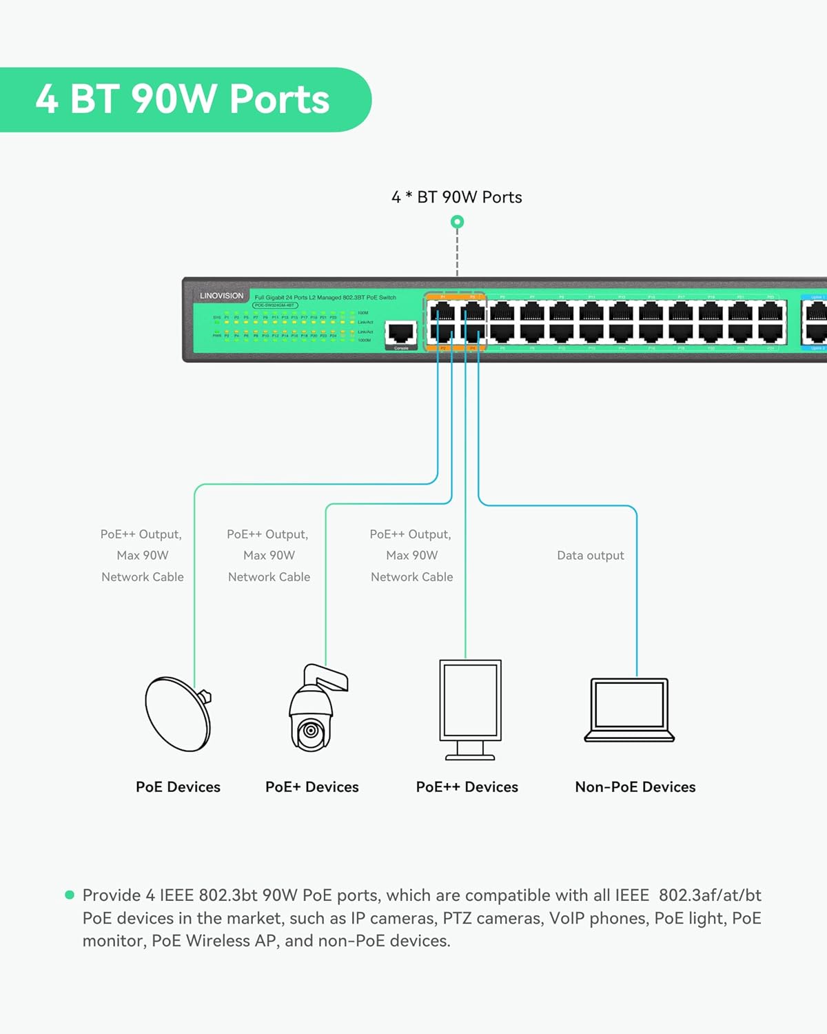
Image 4.1: Illustration of the 4 BT 90W PoE ports and their compatibility with different PoE device types.

Image 4.2: Visual representation of the switch's PoE power distribution and total budget.
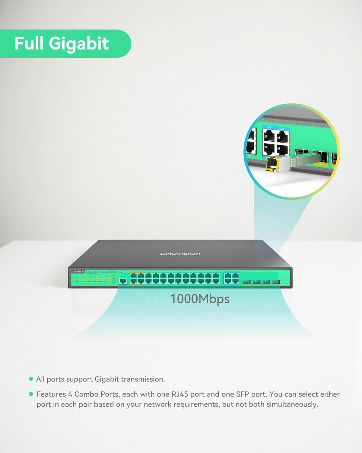
Image 4.3: Illustration of the switch's full Gigabit speed and the flexibility of its combo ports.

Слика 4.4: На пр.ample of the L2 Management interface, demonstrating various configurable network settings.
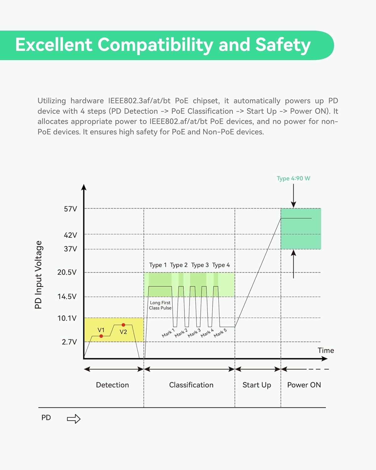
Image 4.5: Graph detailing the safe power negotiation process for PoE devices.

Слика 4.6: Готовоview of the switch's robust physical design and protective features.
5. Поставување
This section guides you through the initial setup of your LINOVISION PoE Switch.
5.1 Распакување и првична инспекција
Carefully unbox the switch and its accessories. Inspect all components for any signs of damage during transit. Refer to the 'Package Contents' section to ensure all items are present.
Video 5.1: This video demonstrates the unboxing process of the LINOVISION 24 Port L2 Managed BT 90W PoE Switch, showing how to safely remove the product and its accessories from the packaging.
5.2 Физичка инсталација
- Монтирање: Use the provided rack mount accessories to install the switch into a standard 19-inch server rack, if applicable. Ensure adequate ventilation around the device.
- Заземјување: Connect the ground terminal on the rear panel to a proper earth ground using a grounding wire for electrical safety.
- Поврзување за напојување: Connect the power adapter to the AC input on the rear panel and then to a suitable power outlet. Ensure the power switch is in the OFF position before connecting.
5.3 Мрежни врски
- Connecting PoE Devices: Connect your IEEE 802.3af/at/bt compliant PoE devices (e.g., IP cameras, access points) to the PoE ports (P1-P24) on the front panel using standard Ethernet cables.
- Connecting Non-PoE Devices: Non-PoE network devices can also be connected to the PoE ports; the switch will automatically detect and not supply power to them.
- Врски за довршување: Use the Gigabit Combo Ports (Uplink 1-4) to connect the switch to your core network, router, or other switches. You can use either the RJ45 or SFP port for each combo pair.
- Поврзување на конзолата: For initial configuration or advanced management via CLI, connect a console cable to the Console Port on the front panel and to a computer.
6. Упатства за работа
Once the switch is physically installed and connected, you can begin operation and configuration.
6.1 Вклучување
Flip the power switch on the rear panel to the ON position. The Power Indicator LED on the front panel should illuminate, indicating the device is receiving power. The System Indicator LED will also light up, and PoE/Link indicators will show port status.
6.2 L2 Management Access
The LINOVISION PoE Switch supports various Layer 2 management methods:
- Web-заснован менаџмент: Пристапете до прекинувачот web интерфејс со внесување на нејзината IP адреса во a web browser. The default IP address and login credentials can be found in the full user manual or quick start guide.
- Интерфејс со командна линија (CLI): Connect via the Console Port using a terminal emulator (e.g., PuTTY) for command-line configuration.
- SNMP: The switch can be managed remotely using Simple Network Management Protocol (SNMP) for network monitoring and configuration.
6.3 Key Management Functions
Преку интерфејсот за управување, можете да конфигурирате:
- VLAN (Виртуелна локална мрежа): Сегментирајте ја вашата мрежа за подобрена безбедност и перформанси.
- QoS (Квалитет на услуга): Дајте приоритет на мрежниот сообраќај за критични апликации.
- ACL (Список за контрола на пристап): Филтрирајте го мрежниот сообраќај врз основа на дефинирани правила.
- PoE Control: Enable/disable PoE on specific ports, monitor power consumption, and schedule PoE operation.
7. Одржување
Regular maintenance ensures the longevity and optimal performance of your LINOVISION PoE Switch.
- Чистење: Чувајте го прекинувачот чист и без прашина. Користете мека, сува крпа за чистење. Не користете течни или аеросолни средства за чистење.
- Вентилација: Уверете се дека отворите за вентилација не се блокирани. Соодветниот проток на воздух е клучен за да се спречи прегревање.
- Ажурирања на фирмверот: Периодично проверувајте го LINOVISION webстраница за ажурирања на фирмверот. Ажурирањето на фирмверот може да ги подобри перформансите, да додаде нови функции и да ги реши безбедносните ранливости.
- Еколошки услови: Operate the switch within the recommended temperature and humidity ranges specified in the 'Specifications' section.
8 Смена на проблеми
If you encounter issues with your LINOVISION PoE Switch, refer to the following common troubleshooting steps:
- Без моќност:
- Check if the power cable is securely connected to the switch and the power outlet.
- Осигурајте се дека прекинувачот за напојување на задниот панел е во положба ВКЛУЧЕНО.
- Проверете дали штекерот е функционален.
- Нема мрежна конекција:
- Проверете ги Ethernet каблите за безбедни врски и оштетувања.
- Verify the Link/Act LED indicators for the connected ports are active.
- Ensure IP address settings are correct if configured manually.
- PoE уредот не прима напојување:
- Confirm the connected device is IEEE 802.3af/at/bt compliant.
- Check the PoE/Link indicator for the specific port.
- Ensure the total PoE budget (370W) is not exceeded by all connected devices.
- Verify PoE is enabled for the port in the L2 management interface.
- Пристапување Web Interface Issues:
- Осигурајте се дека вашиот компјутер е на истиот мрежен сегмент како и прекинувачот.
- Try pinging the switch's IP address to confirm network reachability.
- Исчистете го кешот на прелистувачот или обидете се со друг прелистувач.
If these steps do not resolve the issue, please consult the full user manual or contact LINOVISION technical support.
9. Спецификации
Detailed technical specifications for the LINOVISION 24 Ports L2 Managed PoE Switch (POE-SW324GM-4BT).
| Атрибут | Вредност |
|---|---|
| Димензии на производот | 17.32 x 11.42 x 1.75 инчи (440 mm x 290 mm x 44.5 mm) |
| Тежина на ставката | 9.28 фунти (4.21 кг) |
| Број на модел на ставка | POE-SW324GM-4BT |
| Производител | ЛИНОВИЗИЈА |
| PoE пристаништа | 4x BT 90W PoE++ ports, 20x AT 30W PoE+ ports |
| Врски пристаништа | 4x Gigabit Combo Ports (RJ45/SFP) |
| Вкупен буџет на PoE | 370 W |
| Капацитет на префрлување | 64 Gbps |
| Управување | L2 Managed (WEB, CLI, SNMP), supports VLAN, QoS, ACL, PoE Control |
| Прилог | Full Metal, IP40 |
| Заштита од пренапони | 6 KV |
10. Гаранција и поддршка
LINOVISION products are designed for reliability and performance. For warranty information, technical support, or service inquiries, please refer to the official LINOVISION website or contact their customer service directly. Details regarding warranty periods and support channels are typically provided with your purchase documentation or on the manufacturer's webсајт.
Manufacturer: LINOVISION
За дополнителна помош, посетете: LINOVISION Official Store on Amazon